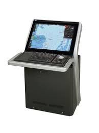
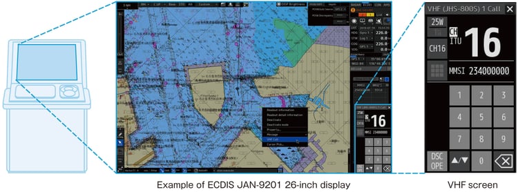
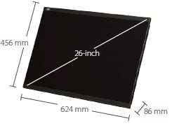
JRC JAN-9201C Multi Function Display ECDIS (Simplified) with 26" display
Provide a smooth operating environment ensured
by high-speed chart drawing
Conforming to the latest IMO performance standards with Marine Equipment
Directive (MED) certification.
Ensuring intuitive and easy-to-use display and operation performance
reflecting professional user's voices.
Integrating route editing and route safety checking to support safer route
plans.
Delivered with a software license allowing an expansion tailored to each
operational requirement for a wide
variety of optional features.
Providing the J-Marine Cloud service that collectively supports the updating
of charts.
ECDIS type-specific training (TST) is provided by a variety of organizations
around the world on behalf of JRC.
Features
Sophisticated user interface
The Electronic Chart Display and Information System (ECDIS) is a geographic
information system for voyage planning and route monitoring to support the
safety navigation of ships at sea.
The ECDIS onboard a ship uses images obtained from the automatic identification
system (AIS), radar system, and collision avoidance target tracking (TT) system
and superposes the images with navigational chart information, thus accurately
displaying dynamic information on other ships around. Also the ECDIS plays
central roles in the safe navigation of the ship and provides safety functions,
including the generation of warnings when the ship approaches dangerous areas.
The ECDIS is useful for marine accident avoidance and serves as equipment
indispensable to the safe navigation of ships.
Mandatory installation of ECDIS
In response to the latest revision of the International Convention for the
Safety of Life at Sea (SOLAS), the International Maritime Organization (IMO)
enforced the mandatory installation of the ECDIS on oceangoing passenger ships
with 500 gross tons or more and tankers and cargo ships with 3,000 gross tons or
more in a stepwise manner in and after July 2012. This mandatory decision
requires conventional paper charts or an additional ECDIS as a backup to the
primary ECDIS if a ship uses the primary ECDIS as main navigational equipment.
(Requirements for the equipment and operation qualification are subject to
approval from the country with which the ship is registered and recommendations
from the classification society of the ship.)
Type
Size
Newbuild
Existing
Passenger ship
> 500
July 2012
July 2014
Tanker
> 3,000
July 2012
July 2015
Cargo ship
> 3,000
July 2014
-
> 10,000
July 2013
July 2018
> 20,000
July 2013
July 2017
> 50,000
July 2013
July 2016
Regulations and major specifications
This equipment conforms to the requirements set out in the IMO's resolution
MSC.191 (79) for display-related voyage information adopted in December 2004 and
the IMO Resolution MSC.232 (82) for ECDIS performance standards adopted in
December 2006.
Other specifications of the ECDIS are shown below.
Electronic chart display function/Radar overlay function : IEC 61174
Display-related voyage information : IEC 62288
Track control system (TCS) function *1 :
IEC 62065
*1 Contact your JRC representative for supporting autopilot models.
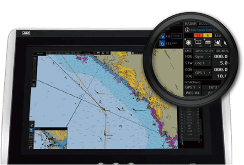
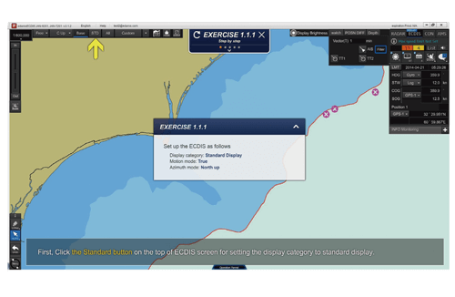
Sophisticated user interface
The JAN-9201/7201 incorporates a new user interface (named jGUI) for an
intuitive, easy-to-use, simple menu system based on the display of icons.
This interface always displays critical data in fixed positions on the
screen while icon-based menu display informs users of corresponding
functions straightaway. Furthermore, target tracking (TT) and AIS symbols
feature pop-up displays while mouseover on the target showing their main
data at a glance.
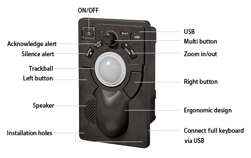
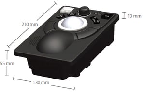
Easy-to-use operating unit
The newly designed trackball supports all the operation of the equipment.
Users will be alerted with alarms from the operating unit and color
changes under situations that require attention.
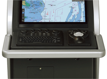
Optional keyboard
The ECDIS will be operable like conventional models by connecting an
optional operating unit that incorporates dedicated function buttons,
control knobs and a full keyboard adopting the QWERTY layout.
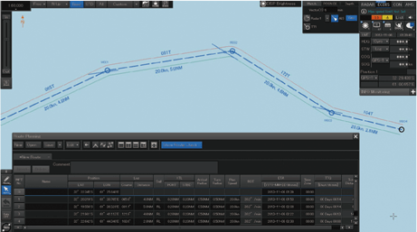
Route editing screen example
Route editing and safety checking
JRC's new ECDIS model JAN-9201/7201 has integrated route editing, which
was conventionally divided into two segments, i.e., graphics input and
numeric table input areas, into one. Waypoints, if specified, on a
navigational chart are immediately quantified and added to the numeric
editing table, and the numeric data on the waypoints that is input into
the editing table is immediately reflected on the navigational chart. Up
to four routes can be edited at the same time, and a portion cut out of
any route can be combined and the routes can be all or partly replaced or
edited.
Furthermore, a safety check on edited route data is possible with a click
of a button. Detected error information items, if any, are listed and
displayed, and the corresponding route portions are highlighted in the
chart and table, which can be confirmed at a glance to take remedial
measures.
Function
Functional expansion
The equipment incorporates a variety of optional functions that will be
available with software licenses added. Software licenses can be added before or
after the radar comes into operation. Therefore, the radar can be customized to
match the actual operating conditions.
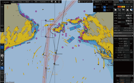
Example of additional display of radar pverlay function
Optional functions
Expansion of AIS display targets (500 → 1000)
Radar overlay function*1
TCS support*2
S-Joy control support*3
*1 : The radar overlay function requires an optional radar interface circuit
and radar image signal input.
*2 : The track control system (TCS) function requires auto pilot connections
in addition. For details, including corresponding models, contact your JRC
representative.
*3 : For autopilot models connectable to the S-Joy control panel, contact
your JRC representative.
Correspond to the major chart
The JAN-9201/7201 supports the display of major electronic navigational charts (ENCs),
including those provided by ADMIRALTY Vector Chart Service (AVCS) (S-57 Ed
3.0/3.1 and S-63), NAVTOR ENC Service, and C-MAP ADMIRALTY ENC Service as well
as ADMIRALTY Raster Chart Service (ARCS). Also, it supports advanced features
provided with ENCs, such as the Admiralty Information Overlay (AIO) of AVCS by
the United Kingdom Hydrographic Office (UKHO) and Dynamic Licensing of Jeppesen
ENC service.
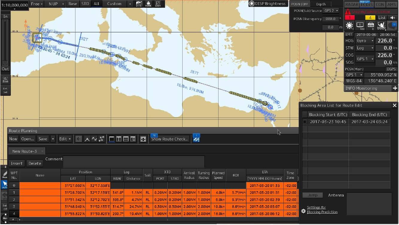
Example satellite transmission blocking area display
Satellite transmission blocking area display*5>
The equipment offers a function for confirming areas where JRC
INMARSAT FBB and INMARSAT GX*6 equipment
cannot communicate with satellites. The equipment can display
satellite antenna reception levels, blocking conditions, and
transmission suspension*7.
When connections with antennas are lost, this function can be used to
check whether it is a temporary transmission outage or it is caused by
a device malfunction. When performing route planning, this function
makes it possible to confirm in advance if there are any parts of the
route where satellite communication is not possible and to avoid
losing contact.
*5 : Satellite transmission blocking area display is option, contact
your JRC representative.
*6 : The INMARSAT FBB and INMARSAT GX support the JUE-251/501 and the
JUE-60GX.
*7 : Transmission suspension supports only the JUE-60GX.
VHF remote operation by ECDIS
The ECDIS offers a VHF remote operation function*8.
This can be used to configure channels on the VHF unit or to perform DSC
calls using AIS targets on the radar PPI screen. Features such as the
wireless speaker mic*9 make
it possible to communicate with other ships even when away from the VHF
equipment.
*8 : The VHF supports the JHS-800S.
*9 : Wireless speaker mic is option for the JHS-800S.
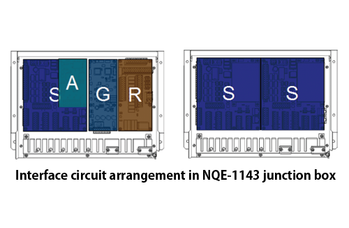
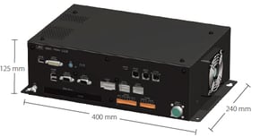
Sensor data sharing
The central control unit is provided with the minimum required external
interfaces specified by Marine Equipment Directives (MEDs), and other sensor
data is received through the bridge network (LAN) from the interface
circuits. The interface circuits are designed to be shared by a number of
new-type navigation devices, and each type of interface circuit can be
combined and selected according to each signal format and the number of
connections.
Interface circuits
S : SLC (Serial LAN interface circuit): IEC 61162-2 � 2; IEC 61162-1 � 8;
Contact input
point � 4; Contact output point x 8
A : AOC (Analog option circuit)*10:
-10 to 10VDC or 4 to 20mA � 4
G : GIF (Gyro interface circuit): Gyro signals (Sync and Step); Ship speed
pulse signals (100 to 800 pp)
R : RIF (Radar interface circuit): Interswitch connection � 1; Slave video
input � 1
*10 : The installation of the AOC requires a serial LAN interface circuit (SLC).
Type-specific training (TST)
Type-specific training (TST)
Unlike JRC's conventional ECDIS models, this ECDIS has adopted a new
operation system and a TST program supporting the new operation system
is required. The TST for the new ECDIS is given at JRC's major
branches, agents, and training institutions around the world. The
training will be given onboard or offices by instructors dispatched at
the request of customers.
Furthermore, PC software is available for users' self-learning at home
or onboard. For more information about TST, contact your JRC
representative.
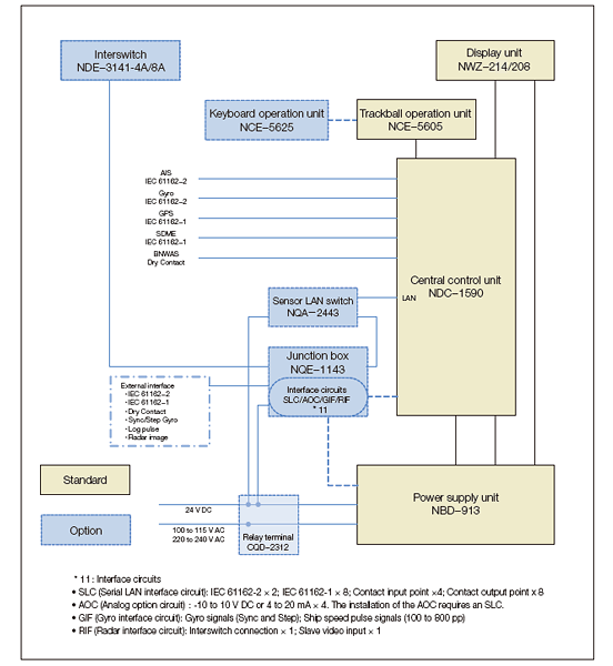
Block diagram
In the box
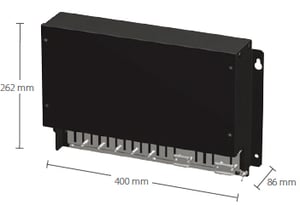
Central control unit
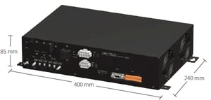
Power supply unit
Display unit
Trackball operation unit
Options
Keyboard operation unit
Sensor LAN switch
Junction box
Serial LAN interface circuit
Analog option circuit
Gyro interface circuits
Radar interface circuit
Relay terminal block
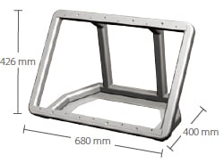
Display unit mount kit
Interswitch (4 ch/8 ch)
eToken*12
*12 : For C-MAP ADMIRALTY ENC Service and C-MAP Professional+.
Waypoint addition/deletion/edition
Alternative route creation
Route copy
Connection between routes
Import/export (in CSV)
Safety check
Yes
Number of routes displayed
Four types max.
Navigation-monitoring function
Own ship
Monitoring for position, wake, and dragging anchor
Route monitoring
Water depths, obstacles, approaching prohibited areas, course deviation,
waypoints, and arrival time
Other ship monitoring
TT display 200 targets max. (100 targets per radar and responding to a
maximum of two radars)
AIS display: 500 targets max. (expanding to a maximum 1,000 targets with
an optional function added)
User map
Number of display points
100,000 points (marks and lines)
Import/Export
Possible with USB memory
Other functions
Data display function
Conning data block display
Self-diagnostic function
Standard
Remote maintenance function
Standard
Playback
Navigation data (3 months max.)
Logbook (3 months max.)
**The price is subject to change at anytime without any notice. We
are not responsible for any typographical errors. Any products can be
cancelled from sale at any time.
** All Products sold here are Brand New unless specified
Otherwise and come with Full Manufacturer's Warranty
WARNING:
This product can expose you to chemicals including Di-n-hexyl Phthalate (DnHP)
which is known to the State of California to cause reproductive harm, and
Vinyl Chloride which is known to the State of California to cause cancer. For
more information go to P65Warnings.ca.gov.
__________________________________________________________________________________________


