Newmar�s Phase Three Series
Battery Chargers employ �Smart� battery charging technology for 12 volt systems
aboard marine applications including workboats, military vessels, commercial
vessels, and recreational craft. These chargers interact with batteries
providing the optimum three stage charge process for fast recovery and
conditioning, maximizing performance and extending battery life.
A selector switch adjusts
output voltage to adapt to gel-cell/flooded lead-acid/AGM battery types. An
optional temperature compensation sensor also adjusts output for ideal voltage
based on changes in the batteries� ambient temperature. All models are housed in
a rugged stainless steel case with a durable white powder coat finish, and the
internal circuitry is polyurethane coated for maximum corrosion resistance.
Features
-
�Smart� circuitry provides
three stage charging � bulk, absorption, float
-
Gel-Cell/Flooded Lead-acid/AGM
battery type switch selects optimum charge/float voltages
-
Multiple isolated output
banks; ammeter indicates total output current. (Except PT-7)
-
Optional sensor adjusts
output voltage based on battery temperature. (Except PT-7)
-
Current limiting-prevents
damage from overloading
-
Clean well regulated output
can be used as a power supply; can power loads directly without a battery in
line
-
Built to last � rugged
stainless steel case with a durable white powder coat finish with an optional
drip shield and marinized internal circuitry
-
Protection: Current Limiting,
Thermal Protection, Forced Air Cooling, Drip Shield
-
ABS type approval for battery
charging and power supplies
Specifications
|
12 Volt Models |
PT-7 |
PT-14W |
PT-25W |
PT-40U |
PT-80 |
Input VAC
(50-60 Hz.) |
88-132 or
176-264 |
85-264 |
90-132 or
180-264 |
90-264 |
90-264 |
Input Amps
@ Full Load |
|
|
@ 115 VAC |
2 |
2.8 |
6.5 |
6.8 |
12 |
|
@ 230 VAC |
1 |
1.4 |
4 |
3.4 |
7 |
|
P.F. Rating |
>.65 |
.93@230V
.98@115V |
.7 |
.98 @ 115V
.95 @ 230V |
.95@230V
.98@115V |
|
Max Output Amps |
7 |
14 |
25 |
40 |
80 |
|
Output Banks |
2 |
3 |
3 |
3 |
3 |
Battery Capacity
(Amp-Hours) |
14-70 |
28-140 |
50-250 |
80-400 |
160-800 |
Operating Temp.
Rating Reference |
T-1 |
T-2 |
T-4 |
T-5 |
T-7 |
|
Case Size Ref. |
A-1 |
A-2 |
A-2 |
A-3 |
A-5 |
|
Weight; Lbs./Kg. |
3.2/1.5 |
8/4 |
8.2/4 |
11/6 |
15.2/7 |
Optional Temp.
Sensor Model |
N/A |
TCS-12/24 |
TCS-12/24 |
TCS-12/24 |
TCS-12/24 |
|
Remote Panel Model |
N/A |
RP |
RP |
RP |
RP |
|
Equalize Option |
No |
Yes |
Yes |
No |
Yes |
|
Output Indicator Ref. |
M-1 |
M-3 |
M-3 |
M-3 |
M-3 |
|
Compliance Ref. |
CG, CE |
CG, CE |
CG |
CG, CE |
CE |
Temperature Rating References
| |
Temperature |
Derate Linearly From |
|
T-1 |
-10˚ C to +45˚ C |
100% @ 0˚ C to 80% @ -10˚ C |
|
T-2 |
-10˚ C to +60˚ C |
100% @ 40˚ C to 60% @ 60˚ C |
|
T-3 |
-10˚ C to +60˚ C |
100% @ 40˚ C to 60% @ 60˚ C |
|
T-4 |
-20˚ C to +60˚ C |
@ 50˚ C to 60% @ 60˚ C |
|
T-5 |
-20˚ C to +70˚ C |
100% @ 45˚ C to 50% @ 70˚ C |
Case Size References
|
Ref |
Inches |
Centimeters |
|
H* |
W |
D* |
H* |
W |
D* |
|
A-1 |
10.5 |
5.0 |
2.8 |
26.7 |
12.7 |
7.1 |
|
A-2 |
11.2A |
7.7 |
4.75A |
31.8A |
19.6 |
12.1A |
|
A-3 |
13.85B |
9.5 |
4.8B |
35.2B |
24.1 |
12.2B |
|
A-5 |
14.8C |
9.6 |
5.6C |
37.6C |
24.4 |
14.2C |
*With Dripshield Installed:
A Add 1.1″ (2.8 cm) to height and .92″ (2.3 cm) to depth
B Add .75″ (1.9 cm) to height and 1.35″ (3.4 cm) to depth
C Add 1″ (2.54 cm) to height and .5″ (1.27 cm) to depth |
Nominal Output Voltages at Gel/Flooded Switch Settings
(without Temperature Compensation)
|
Setting |
Charge @ 50% load |
Float @ .5 amp load |
|
Gel-Cell |
14.0 VDC |
13.6 VDC |
|
Flooded/AGM |
14.2 VDC |
13.4 VDC |
Compliance References
CG: USCG
CFR 183.410 (Ignition protected)
CE: Carries
the CE mark
ABS: PT
Series meet SVR 2009 4-8-3/5.9, Under 90 meters Rules 2006 4-6-4/7.19, and HSNC
2007 4-8-3/5.13.
Options
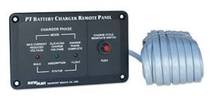
Remote Panel, model RP, for
use with all models except PT-7 and PT-40U
LED�s indicate charger output stage. Manual re-initialization of three stage
charge cycle. With 25′ of cable. Panel dimensions: 3″ H x 4.75″ W
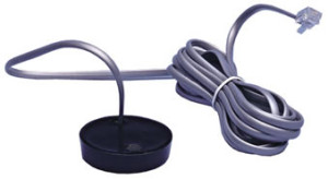
Temperature Compensation
Sensor, Model TCS 12/24, for use with all models except PT 7
-5 mV per cell˚ C
25′ cable (40�cable optional)


