


Sonar Tutorial
People have been fishing for thousands of years. Every person fishing has had
the same problem - finding fish and getting them to bite. Although sonar can�t
make the fish bite, it can solve the problem of finding fish. You can�t catch
them if you�re not fishing where they are - and the Lowrance sonar will prove
it
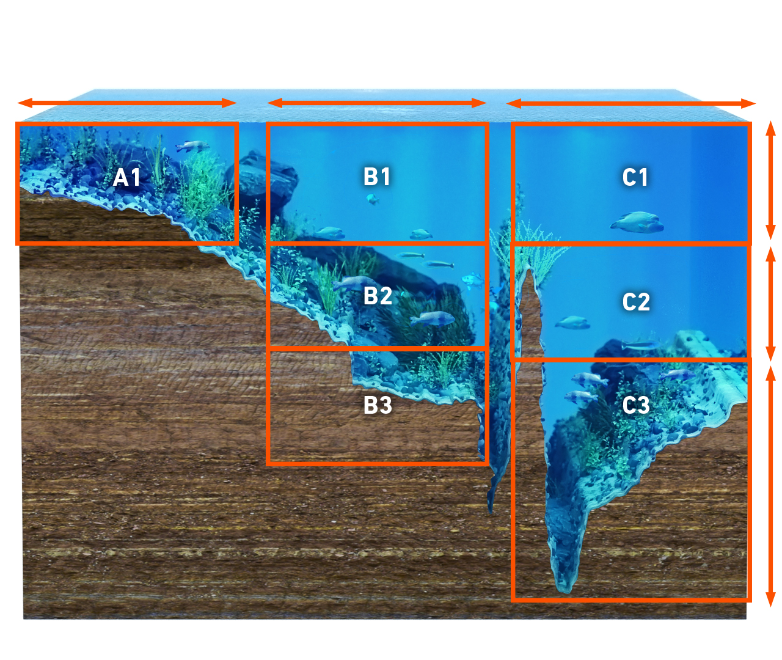
In the late 1950s, Carl Lowrance and his sons Arlen and Darrell began scuba
diving to observe fish and their habits. This research, substantiated by local
and federal government studies, found that about 90 percent of the fish
congregated in 10 percent of the water on inland lakes. As environmental
conditions changed, the fish would move to more favorable areas. Their dives
confirmed that most species of fish are affected by underwater structure (such
as trees, weeds, rocks, and drop-offs), temperature, current, sunlight and
wind. These and other factors also influence the location of food (baitfish,
algae and plankton). Together, these factors create conditions that cause
frequent relocation of fish populations.
During this time, a few people were using large, cumbersome sonar units on fishing boats. Working at low frequencies, these units used vacuum tubes which required car batteries to keep them running. Although they would show a satisfactory bottom signal and large schools of fish, they couldn�t show individual fish. Carl and his sons began to conceptualize a compact, battery operated sonar that could detect individual fish. After years of research, development, struggle and simple hard work, a sonar was produced that changed the fishing world forever.
Out of this simple beginning, a new industry was formed in 1957 with the sale of the first transistorized sportfishing sonar. In 1959, Lowrance introduced �The Little Green Box,� which became the most popular sonar instrument in the world. All transistorized, it was the first successful sportfishing sonar unit. More than a million were made until 1984, when it was discontinued due to high production costs. We�ve come a long way since 1957. From �little green boxes� to the latest in sonar and GPS technology, Lowrance continues to lead in the world of sportfishing sonar.

How it Works

The word "sonar" is an abbreviation
for "SOund, NAvigation and Ranging." It was developed as a means of tracking
enemy submarines during World War II. A sonar consists of a transmitter,
transducer, receiver and display.
In the simplest terms, an electrical impulse from a transmitter is converted
into a sound wave by the transducer and sent into the water. When this wave
strikes an object, it rebounds. This echo strikes the transducer, which
converts it back into an electric signal, which is amplified by the receiver
and sent to the display. Since the speed of sound in water is constant
(approximately 4800 feet per second), the time lapse between the transmitted
signal and the received echo can be measured and the distance to the object
determined. This process repeats itself many times per second.
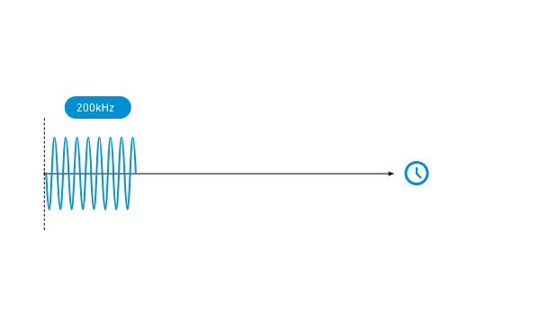
The frequencies most often used by Lowrance in our sonar are 192 - 200 kHz
(kilohertz); we also make some units that use 50 kHz. Although these
frequencies are in the sound spectrum, they�re inaudible to both humans and
fish. (You don�t have to worry about the sonar unit spooking the fish - they
can�t hear it.)
As mentioned earlier, the sonar unit sends and receives signals, then �prints�
the echo on the display. Since this happens many times per second, a
continuous line is drawn across the display, showing the bottom signal. In
addition, echoes returned from any object in the water between the surface and
bottom are also displayed. By knowing the speed of sound through water (4800
feet per second) and the time it takes for the echo to be received, the unit
can show the depth of the water and any fish in the water.
Total System Performance

There are four facets to a good sonar unit:
- High
power transmitter.
-
Efficient transducer.
-
Sensitive receiver.
- High
resolution/contrast display.
We call this our "Total System
Performance" specification. All of the parts of this system must be designed
to work together, under any weather condition and extreme temperatures.
High transmitter power increases the probability that you will get a return
echo in deep water or poor water conditions. It also lets you see fine detail,
such as bait fish and structure.
The transducer must not only be able to withstand the high power from the
transmitter, but it also has to convert the electrical power into sound energy
with little loss in signal strength. At the other extreme, it has to be able
to detect the smallest of echoes returning from deep water or tiny bait fish.
The receiver also has an extremely wide range of signals it has to deal with.
It must dampen the extremely high transmit signal and amplify the small
signals returning from the transducer. It also has to separate targets that
are close together into distinct, separate impulses for the display.
The display must have high resolution (vertical pixels) and good contrast to
be able to show all of the detail crisply and clearly. This allows fish arches
and fine detail to be shown.
Frequency
Most Lowrance sonar units today operate at 192 or 200 kHz
(kilohertz), with a few using 50 kHz.
There are advantages to each frequency, but for almost all freshwater
applications and most saltwater applications, 192 or 200 kHz is the best
choice. It gives the best detail, works best in shallow water and at speed,
and typically shows less "noise" and undesired echoes. Target definition is
also better with these higher frequencies. This is the ability to display two
fish as two separate echoes instead of one "blob" on the screen.
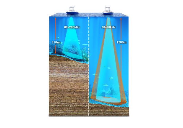
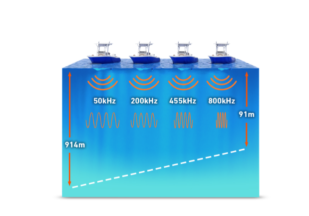
There are some applications where a 50 kHz frequency is best. Typically, a 50
kHz sonar (under the same conditions and power) can penetrate water to deeper
depths than higher frequencies. This is due to water's natural ability to
absorb sound waves. The rate of absorption is greater for higher frequency
sound than it is for lower frequencies. Therefore, you'll generally find 50
kHz used in deeper saltwater applications. Also, 50 kHz transducers typically
have wider coverage angles than 192 or 200 kHz transducers. This
characteristic makes them useful in tracking multiple downriggers. Thus, even
when these downriggers are in relatively shallow depths, 50 kHz is preferred
by many fishermen. In summary, the differences between these frequencies are:
| 192 or 200 kHz | 50 kHz |
|
|
Transducers
The transducer is the sonar unit's "antenna." It converts electric energy from
the transmitter to high frequency sound. The sound wave from the transducer
travels through the water and bounces back from any object in the water. When
the returning echo strikes the transducer, it converts the sound back into
electrical energy which is sent to the sonar unit's receiver. The frequency of
the transducer must match the sonar unit's frequency. In other words, you
can't use a 50 kHz transducer or even a 200 kHz transducer on a sonar unit
designed for 192 kHz! The transducer must be able to withstand high
transmitter power impulses, converting as much of the impulse into sound
energy as possible. At the same time, it must be sensitive enough to receive
the smallest of echoes. All of this has to take place at the proper frequency
and reject echoes at other frequencies. In other words, the transducer must be
very efficient.
Crystal
The active element in a transducer is a man-made crystal (lead
zirconate or barium titanate). To make these crystals the chemicals are mixed,
then poured into molds. These molds are then placed in an oven which "fires"
the chemicals into the hardened crystals. Once they've cooled, a conductive
coating is applied to two sides of the crystal. Wires are soldered to these
coatings so the crystal can be attached to the transducer cable. The shape of
the crystal determines both its frequency and cone angle. For round crystals
(used by most sonar units), the thickness determines its frequency and the
diameter determines the cone angle or angle of coverage (see Cone Angles
section). For example at 192 kHz, a 20 degree cone angle crystal is
approximately one inch in diameter, whereas an eight degree cone requires a
crystal that is about two inches in diameter. That's right. The larger the
crystal's diameter - the smaller the cone angle. This is the reason why a
twenty degree cone transducer is much smaller than an eight degree one - at
the same frequency.
Housings
Transducers come in all shapes and sizes. Most transducers are made
from plastic, but some thru-hull transducers are made from bronze. As shown in
the previous section, frequency and cone angle determine the crystal's size.
Therefore, the transducer's housing is determined by the size of the crystal
inside.
For more information on transducer types and their applications see The Transducer Selection Guide.
Speed and the Transducer
![]()
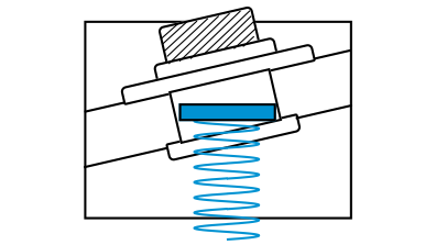
Cavitation is a major obstacle to
achieving high speed operation. If the flow of water around the transducer is
smooth, then the transducer sends and receives signals normally. However, if
the flow of water is interrupted by a rough surface or sharp edges, then the
water flow becomes turbulent. So much so that air becomes separated from the
water in the form of bubbles. This is called "cavitation." If these air
bubbles pass over the face of the transducer (the part of the housing that
holds the crystal), then "noise" is shown on the sonar unit's display. You
see, a transducer is meant to work in water - not air. If air bubbles pass
over the transducer's face, then the signal from the transducer is reflected
by the air bubbles right back into it. Since the air is so close to the
transducer, these reflections are very strong. They will interfere with the
weaker bottom, structure, and fish signals, making them difficult or
impossible to see.
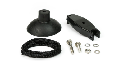
The solution to this problem is to make a transducer housing that will allow
the water to flow past it without causing turbulence. However, this is
difficult due to the many constraints placed upon the modern transducer. It
must be small, so that it doesn't interfere with the outboard motor or its
water flow. It must be easy to install on the transom so that a minimum of
holes need to be drilled. It must also "kick-up" without damage if struck by
another object. Again, the patented design of the HS-WS transducer is
Lowrance's latest improvement in high-speed transducer technology. It combines
high speed operation with easy installation and will "kick-up" if struck by an
object at high speed.
The cavitation problem is not limited to the shape of the transducer housing.
Many boat hulls create air bubbles that pass over the face of a transom
mounted transducer. Many aluminum boats have this problem due to the hundreds
of rivet heads that protrude into the water. Each rivet streams a river of air
bubbles behind it when the boat is moving, especially at high speed. To fix
this problem, mount the face of the transducer below the air bubbles
streaming from the hull. This typically means you have to mount the
transducer's bracket as far down as possible on the transom.
Transducer Cone Angles
The transducer concentrates the sound into a beam. When a pulse of
sound is transmitted from the transducer, it covers a wider area the deeper it
travels. If you were to plot this on a piece of graph paper, you would find
that it creates a cone shaped pattern, hence the term "cone angle." The sound
is strongest along the center line or axis of the cone and gradually
diminishes as you move away from the center.
In order to measure the transducer's cone angle, the power is first measured
at the center or axis of the cone and then compared to the power as you move
away from the center. When the power drops to half (or -3db[decibels] in
electronic terms), the angle from that center axis is measured. The total
angle from the -3db point on one side of the axis to the -3db point on the
other side of the axis is called the cone angle.
This half power point (-3db) is a standard for the electronics industry and
most manufacturers measure cone angle in this way, but a few use the -10db
point where the power is 1/10 of the center axis power. This gives a greater
angle, as you are measuring a point further away from the center axis. Nothing
is different in transducer performance; only the system of measurement has
changed. For example, a transducer that has an 8 degree cone angle at -3db
would have a 16 degree cone angle at -10db.
Although the half power point is the standard for measuring cone angles, fish
detection angles are much larger. Lowrance sonar units have very sensitive
receivers and can detect return echoes from fish, structure or the bottom out
to 60� or more. This means that the fish detection angle is 60� even though
the cone angle is only 20�.

20 degree cone angle | 8 degree
cone angle
Lowrance offers transducers with a variety of cone angles. Wide cone
angles will show you more of the underwater world, at the expense of depth
capability, since it spreads the transmitter's power out. Narrow cone angle
transducers won't show you as much of what's around you, but will penetrate
deeper than the wide cone. The narrow cone transducer concentrates the
transmitter's power into a smaller area. A bottom signal on the sonar unit's
display will be wider on a wide cone angle transducer than on a narrow one
because you are seeing more of the bottom. The wide cone's area is much larger
than the narrow cone.
High frequency (192 - 200 kHz) transducers come in either a narrow or wide
cone angle. The wide cone angle should be used for most freshwater
applications and the narrow cone angle should be used for all saltwater
applications. Low frequency (50 kHz) sonar transducers are typically in the
30 to 45 degree range. Although a transducer is most sensitive inside its
specified cone angle, you can also see echoes outside this cone; they just
aren't as strong. The effective cone angle is the area within the specified
cone where you can see echoes on the display. If a fish is suspended inside
the transducer's cone, but the sensitivity is not turned up high enough to see
it, then you have a narrow effective cone angle. You can vary the effective
cone angle of the transducer by varying the receiver's sensitivity. With low
sensitivity settings, the effective cone angle is narrow, showing only targets
immediately beneath the transducer and a shallow bottom. Turning the
sensitivity control up increases the effective cone angle, letting you see
targets farther out to the sides.
Water and Bottom Conditions
The type of water you're using the sonar in affects its operation to
a large degree. Sound waves travel easily in a clear freshwater environment,
such as most inland lakes.
In salt water however, sound is absorbed and reflected by suspended material
in the water. Higher frequencies are most susceptible to this scattering of
sound waves and can't penetrate salt water nearly as well as lower
frequencies. Part of the problem with salt water is that it's a very dynamic
environment - the oceans of the world. Wind and currents constantly mix the
water. Wave action creates and mixes air bubbles into the water near the
surface, which scatters the sonar signal. Micro-organisms, such as algae and
plankton, scatter and absorb the sonar signal. Minerals and salts suspended in
the water do the same thing. Fresh water also has wind, currents and
micro-organisms living in it that affect the sonar's signal - but not as
severely as salt water.
Mud, sand and vegetation on the bottom absorb and scatter the sonar signal,
reducing the strength of the return echo. Rock, shale, coral and other hard
objects reflect the sonar signal easily. You can see the difference on your
sonar's screen. A soft bottom, such as mud, shows as a thin line across the
screen. A hard bottom, such as rock, shows as a wide line on the sonar's
screen.


Soft Bottom | Hard Bottom
You can compare sonar to using a flashlight in a dark room. Moving
the light around the room, it's easily reflected from white walls and bright,
hard objects. Moving the light onto a darkly carpeted floor returns less light
because the dark color of the carpet absorbs the light, and the rough texture
scatters it, returning less light to your eyes. Adding smoke to the room
(children, don't try this at home!), you'll see even less. The smoke is
equivalent to salt water's effect on the sonar signal.
Water Temperature and Thermodlcines

Water temperature has an important
influence upon the activities of all fish. Fish are cold-blooded and their
bodies are always the temperature of the surrounding water. During the winter,
colder water slows down their metabolism. At this time, they need about a
fourth as much food as they consume in the summer.
Most fish don't spawn unless the water temperature is within rather narrow
limits. The surface water temperature gauge built into many of our sonar units
helps identify the desired surface water spawning temperatures for various
species. For example, trout can't survive in streams that get too warm. Bass
and other fish eventually die out when stocked in lakes that remain too cold
during the summer. While some fish have a wider temperature tolerance than
others, each has a certain range within which it tries to stay. Schooling fish
suspended over deep water lie at the level that provides this temperature. We
assume they are the most comfortable here.

The temperature in a lake is seldom
the same from the surface to the bottom. Usually there is a warm layer of
water and a cooler layer. Where these layers meet is called a thermocline. The
depth and thickness of the thermocline can vary with the season or time of
day. In deep lakes there may be two or more thermoclines. This is important
because many species of game fish like to suspend in, just above, or just
below the thermocline. Many times bait fish will be above the thermocline
while larger game fish will suspend in or just below it. Fortunately, this
difference in temperatures can be seen on the sonar screen. The greater the
temperature differential, the denser the thermocline shows on the screen.
Operation
Automatic

After starting your boat, go to a protected cove and stop. Leave the engine on. You may want to take a partner along to operate the boat while you learn how to use the sonar. Press the sonar unit's ON key and idle slowly around the cove. You'll probably see a screen similar to the one to the left. The dashed line at the top of the screen represents the surface. The bottom shows in the lower part of the screen. The current water depth (33.9 feet) shows in the upper left corner of the screen. The depth range in this example is 0 to 40 feet. Since the unit is in the automatic mode, it continually adjusts the range, keeping the bottom signal on the display.
Fish-Symbol I.D.�

Every Lowrance LCG offers the
convenience of our Advanced Fish-Symbol I.D.�. Activated by the press of a
button, Advanced Fish Symbol I.D.� lets your unit do the work of interpreting
return sonar signals. Advanced Fish Symbol I.D.� works in automatic mode only.
If you turn it on while in manual mode, it will switch to automatic mode. Fish
and other suspended targets are clearly displayed as fish-shaped symbols in
four different sizes.
Advanced Fish Symbol I.D.� is designed to give a simplified, easy to interpret
display of suspended targets that are assumed to be fish. After gaining
experience with your sonar, you will probably turn it off much of the time so
you can see all of the detailed information on fish movement, thermoclines,
schools of baitfish, weed beds, bottom structure, etc.
ASP� (Advanced Signal Processing)
Advanced Signal Processing (ASP�) is another exclusive Lowrance
innovation that uses sophisticated programming and advanced digital
electronics to continually monitor the effects of boat speed, water conditions
and other interference sources - and automatically adjusts the sonar settings
to provide the clearest picture possible.
ASP� sets the sensitivity as high as possible while keeping the screen free of
"noise." It automatically balances sensitivity and noise rejection. The
feature can be turned off and on and will work whether the sonar is in
automatic or manual mode. With ASP� operating behind the scenes you'll spend
less time making routine sonar adjustments and more time spotting fish.
Sensitivity
The sensitivity controls the ability of the unit to pick up echoes. A
low sensitivity level excludes much of the bottom information, fish signals,
and other target information. High sensitivity levels enable you to see this
detail, but it can also clutter the screen with many undesirable signals.
Typically, the best sensitivity level shows a good solid bottom signal with
GRAYLINE� and some surface clutter. When in the automatic mode, the
sensitivity is automatically adjusted to keep a solid bottom signal displayed,
plus a little more. This gives the unit the capability to show fish and other
detail. In automatic mode, the unit also adjusts sensitivity automatically for
water conditions, depth, etc. When you adjust the sensitivity up or down, you
are biasing up or down the normal setting the unit's automatic control would
choose. With ASP� enabled, the automatic mode picks the proper sensitivity
level for 95% of all situations, so it is recommend to always use this normal
mode first. But, for those unusual situations where it is warranted you can
bias it up or down. You can also turn off the automatic sensitivity control
for special uses.
To properly adjust the sensitivity
while the unit is in the manual mode, first change the range to double its
current setting. For example, if the range is 0 - 40 feet, change it to 0 - 80
or 0 - 100 feet. Now increase the sensitivity until a second bottom echo
appears at twice the depth of the actual bottom signal. This "second echo" is
caused by the echo returning from the bottom reflecting off the surface of the
water, making a second trip to the bottom and returning. Since it takes twice
as long for this echo to make two trips to the bottom and back, it shows at
twice the depth of the actual bottom. Now change the range back to the
original scale. You should see more echoes on the screen. If there is too much
noise on the screen, back the sensitivity level down a step or two.
Grayline
GRAYLINE� lets you distinguish between strong and weak echoes. It
"paints" gray on targets that are stronger than a preset value. This allows
you to tell the difference between a hard and soft bottom. For example, a
soft, muddy or weedy bottom returns a weaker symbol which is shown with a
narrow or no gray line. A hard bottom returns a strong signal which causes a
wide gray line.
If you have two signals of equal size, one with gray and the other without,
then the target with gray is the stronger signal. This helps distinguish weeds
from trees on the bottom or fish from structure.
GRAYLINE� is adjustable. Since GRAYLINE� shows the difference between strong
and weak signals, adjusting the sensitivity may also require a different
GRAYLINE� level.
Zoom

You may see fish arches while trolling with the unit in a 0 - 60 foot scale, however it it much easier to see the arches when using the zoom feature. This enlarges all echoes on the screen. Turning the zoom feature on gives you a screen similar to the one at left. The range is 8 - 38 feet, a 30-foot zoom. As you can see, all targets have been enlarged, including the bottom signal. Fish arches (A & B) are much easier to detect, and important structure (C) near the bottom is magnified. This also shows small fish hanging just beneath the surface clutter (D). The above steps are all that's required to manually adjust your sonar unit for optimum fish finding capability. After you've become more familiar with your unit, you'll be able to adjust the sensitivity properly without having to look for a second echo.
Fish Arches
One of the most common questions that we receive is "How do I get
fish arches to show on my screen?" It's really pretty simple to do, but it
does require attention to detail, not only in the way you make the adjustments
to the unit, but to the whole sonar installation.
It also helps to see the Why Fish Arch section below. This explains how arches
are created on your sonar's screen.
Screen Resolution
The number of vertical pixels that the screen is capable of showing
is called Screen Resolution. The more vertical pixels on a sonar's screen, the
easier it will be for it to show fish arches. This plays an important role in
a sonar unit's capability to show fish arches. The chart below lists the pixel
sizes and area they represent down to 50 feet for two different screens.
| PIXEL HEIGHT | PIXEL HEIGHT | |||
| 100 VERTICAL PIXEL SCREEN | 240 VERTICAL PIXEL SCREEN | |||
| RANGE | PIXEL HEIGHT | RANGE | PIXEL HEIGHT | |
| 0-10 feet | 1.2 inches | 0-10 feet | 0.5 inches | |
| 0-20 feet | 2.4 inches | 0-20 feet | 1.0 inches | |
| 0-30 feet | 3.6 inches | 0-30 feet | 1.5 inches | |
| 0-40 feet | 4.8 inches | 0-40 feet | 2.0 inches | |
| 0-50 feet | 6.0 inches | 0-50 feet | 2.5 inches | |
As you can see, one pixel represents a larger volume of water with the unit in the 0 - 100 foot range than it does with the unit in the 0 - 10 foot range. For example, if a sonar has 100 pixels vertically, with a range of 0 - 100 feet, each pixel is equal to a depth of 12 inches. A fish would have to be pretty large to show up as an arch at this range. However, if you zoom the range to a 30-foot zoom (for example from 80 to 110 feet), each pixel is now equal to 3.6 inches. Now the same fish will probably be seen as an arch on the screen due to the zoom effect. The size of the arch depends on the size of the fish - a small fish will show as a small arch, a larger fish will make a larger arch, and so on. Using a sonar unit with a small number of vertical pixels in very shallow water, a fish directly off the bottom will appear as a straight line separate from the bottom. This is because of the limited number of dots at that depth. If you are in deep water (where the fish signal is displayed over a larger distance of boat travel), zooming the display into a 20 or 30 foot window around the bottom shows fish arches near the bottom or structure. This is because you have reduced the pixel size in a larger cone.
![]()
The scrolling or chart speed can also affect the type of arch displayed on the screen. The faster the chart speed, the more pixels are turned on as the fish passes through the cone. This will help display a better fish arch. (However, the chart speed can be turned up too high. This stretches the arch out. Experiment with the chart speed until you find the setting that works best for you.)
Transducer Installation
If you still don't get good fish arches on the screen, it could be the transducer's mounting is incorrect. If the transducer is mounted on the transom, adjust it until its face is pointing straight down when the boat is in the water. If it is angled, the arch won't appear on the screen properly. If the arch slopes up but not down, then the front of the transducer is too high and needs to be lowered. If only the back half of the arch is printed, the nose of the transducer is angled too low and needs to be raised.
Fish Arch Review
1. Sensitivity
Automatic operation with Advanced Signal Processing (ASP�) turned on should give you the proper sensitivity settings but, if necessary, the sensitivity may be increased.
2. Target Depth
The depth of the fish can determine if the fish will arch on the
screen. If the fish is in shallow water, the fish is not in the cone angle
very long, making it difficult to show an arch. Typically, the deeper the
fish, the easier it is to show an arch.
3. Boat Speed
The boat's engine should be in gear at an idle or just above.
Experiment with your boat to find the best throttle location for good arches.
Usually, a slow trolling speed works best.
4. Chart Speed
Use at least 3/4 chart speed or higher.
5. Zoom Size
If you see markings that are possible fish, but they do not arch,
zoom in on them. Using the zoom function lets you effectively increase the
screen's resolution.
Final Notes on Fish Arches
Very small fish probably will not arch at all. Because of water conditions
such as heavy surface clutter or thermoclines, the sensitivity sometimes
cannot be turned up enough to get fish arches. For the best results, turn the
sensitivity up as high as possible without getting too much noise on the
screen. In medium to deep water, this method should work to display fish
arches.
A school of fish will appear as many different formations or shapes, depending
on how much of the school is within the transducer's cone. In shallow water,
several fish close together appear like blocks that have been stacked in no
apparent order. In deep water, each fish will arch according to its size.
Why Fish Arch
The reason fish show as an arch is because of the relationship
between the fish and the cone angle of the transducer as the boat passes over
the fish. As the leading edge of the cone strikes the fish, a display pixel is
turned on. As the boat passes over the fish, the distance to the fish
decreases. This turns each pixel on at a shallower depth on the display. When
the center of the cone is directly over the fish, the first half of the arch
is formed. This is also the shortest distance to the fish. Since the fish is
closer to the boat, the signal is stronger and the arch is thicker. As the
boat moves away from the fish, the distance increases and the pixels appear at
progressively deeper depths until the cone passes the fish.

If the fish doesn't pass directly
through the center of the cone, the arch won't be as well defined. Since the
fish isn't in the cone very long, there aren't as many echoes to display, and
the ones that do show are weaker. This is one of the reasons it's difficult to
show fish arches in shallow water. The cone angle is too narrow for the signal
to arch.
Remember, there must be movement between the boat and the fish to develop an
arch. Usually, this means trolling at a slow speed with the main engine. If
you are anchored or stopped, fish signals won't arch. Instead, they'll show as
horizontal lines as they swim in and out of the cone.
Actual On-The-Water Chart
Recordings
The following chart records are from a Lowrance X-85 liquid crystal
graph sonar. It has 3000 watts of transmitter power, a 240 x 240 pixel screen
and operates at 192 kHz.
X-85 Sample 1

This shows a split-screen view of
the water beneath the boat. The range on the right side of the screen is 0 -
60 feet. On the left, the screen has a 30-foot "zoom" rangeof 9 to 39 feet.
Since the unit is in the automatic mode, (shown by the word "auto" at the top
center of the screen) it picked the ranges to keep the bottom signal on the
screen at all times. The water depth is 35.9 feet.
The unit was used with an HS-WSBK "Skimmer�" transducer mounted on the
transom. The sensitivity level was adjusted to 93% or higher. Chart speed was
one step below maximum.
A. Surface Clutter
The markings at the top of the screen can extend many feet below the
surface. This is called Surface Clutter. It's caused by many things, including
air bubbles created by wind and wave action or boat wakes, bait fish, plankton
and algae. Many times larger fish will be seen feeding on the bait fish and
other food near the surface.
B. GRAYLINE�
GRAYLINE� is used to outline the bottom contour which might otherwise
be hidden beneath trees and brush. It can also give clues to the composition
of the bottom. A hard bottom returns a very strong signal, causing a wide gray
line. A soft, muddy or weedy bottom returns a weaker signal which is shown
with a narrow gray line. The bottom on this screen is hard, composed mainly of
rock.
C. Structure
Generally, the term "structure" is used to identify trees, brush, and
other objects rising from the bottom that aren't part of the actual bottom. On
this screen, "C" is probably a tree rising from the bottom. This record was
taken from a man-made lake. Trees were left standing in several areas when the
lake was built, creating natural habitats for many game fish.
D. Fish Arches
The X-85 has a significant advantage over many competitive units in
that it can show individual fish with the characteristic arched mark on the
screen. (See Why
Fish Arch for more
information.) On this screen, there are several large fish holding just off
the bottom at "D," while smaller fish are hanging in the middle of the screen
and near the structure.
E. Other Elements
The large, partial arch shown at "E" is not a fish. We were trolling
near the entrance to a cove that had hundreds of tires banded together with
wire cables. Other cables anchored the tires to the bottom. The large arch at
"E" was created when we passed over one of the large cables that anchored the
tires.
X-85 Sample 2

This shows a full-screen zoom view
of the water beneath the boat. The range is 8 - 38 feet, which gives a 30-foot
zoom. Since the unit is in the automatic mode, (shown by the word "auto" at
the top center of the screen) it picked the ranges to keep the bottom signal
on the screen at all times. The water depth is 34.7 feet.
The unit was used with an HS-WSBK "Skimmer�" transducer mounted on the
transom. The sensitivity level was adjusted to 93% or higher. Chart speed was
one step below maximum.
A and B. Fish Arches
The X-85 has a significant advantage over many competitive units in
that it can show individual fish with the characteristic arched mark on the
screen. (See Why
Fish Arch for more
information.) On this screen, there are several large fish holding just off
the bottom at "B", while an even larger fish "A" is hanging directly above
them.
C. Structure
Generally, the term "structure" is used to identify trees, brush, and
other objects rising from the bottom that aren't part of the actual bottom. On
this screen, "C" is probably a large tree or trees rising from the bottom.
This record was taken from a man-made lake. Trees were left standing in
several areas when the lake was built, creating natural habitats for many game
fish.
D. Surface Clutter
Surface Clutter "D" at the top of the screen extends below 12 feet in
places. Small fish can be seen beneath the surface clutter. They are probably
feeding.


